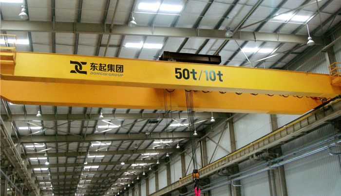
EOT Cranes are industrial machines that are mainly used for materials movements in construction sites, production halls, assembly lines, storage areas, power stations and similar places. EOT Crane design features vary widely according to their major operational specifications such as: type of motion of the crane structure, weight and type of the load, location of the crane, geometric features, operating regimes and environmental conditions.

There are various types of overhead cranes with many being highly specialized, but the great majority of installations fall into one of three categories: a) Top running single girder bridge cranes, b) Top running double girder bridge cranes and c) Under-running single girder bridge cranes. Electric Overhead Traveling (EOT) Cranes come in various types:
1) single girder cranes - The crane consists of a single bridge girder supported on two end trucks. It has a trolley hoist mechanism that runs on the bottom flange of the bridge girder.
2) Double Girder Bridge Cranes - The crane consists of two bridge girders supported on two end trucks. The trolley runs on rails on the top of the bridge girders.
3) gantry cranes - These cranes are essentially the same as the regular overhead cranes except that the bridge for carrying the trolley or trolleys is rigidly supported on two or more legs running on fixed rails or other runway. These “legs” eliminate the supporting runway and column system and connect to end trucks which run on a rail either embedded in, or laid on top of, the floor.
4) Monorail - For some applications such as production assembly line or service line, only a trolley hoist is required. The hoisting mechanism is similar to a single girder crane with a difference that the crane doesn’t have a movable bridge and the hoisting trolley runs on a fixed girder. Monorail beams are usually I-beams (tapered beam flanges).
EOT Crane Working Principle system consists of three working movements: crane hook up and down lifting, trolley lateral movement and crane long traveling longitudinal motion.
Crane hook up and down lifting, trolley lateral movement and crane long traveling longitudinal motion Crane hook up and down lifting, trolley lateral movement and crane long traveling longitudinal motion
1.Transmission of hoisting system: the driving force of hoisting mechanism is from motor. It transmits power to the high speed shaft end of reducer by gear coupling, compensation shaft and brake-wheel coupling. Then through reducer to reduce the high revolution of motor to the required revolution, and output by low-speed shaft of reducer. The ring gear of drum transmit driving force to drum set, then through wire ropes and pulleys drive crane hook up and down, so as to finish the lifting of the heavy objects up and down.
2.Transmission of crane Trolley traveling system: the driving force of crane trolley is from motor. It transmits power to the high speed shaft end of reducer by brake-wheel coupling, compensation shaft and half gear coupling. Then through reducer to reduce the high revolution of motor to the required revolution, and output by low-speed shaft of reducer. And then by half gear coupling, compensation shaft, the half gear coupling joint with trolley driving wheels, so as to drive the trolley driving wheels rotating, so that finish trolley transport heavy objects by lateral movement.
3.Transmission of crane traveling system: the driving force of crane trolley is from motor. It transmits power to the high speed shaft end of reducer by brake-wheel coupling, compensation shaft and half gear coupling. Then through reducer to reduce the high revolution of motor to the required revolution, and output by low-speed shaft of reducer. And then by full gear coupling joint with crane driving wheel shaft, so as to drive the crane driving wheels rotating, so that finish bridge transport heavy objects by lateral movement.
To select correct crane envelope that will fit in the building foot print, the user must identify and pass on the following key information to the supplier:
Side wall. Crane Span is the horizontal center distance between the rails of the runway on which the crane is to travel. Typically distance is approximate to 500mm less than the width of the building.
How much span a crane requires depends on the crane coverage width dictated by the application.
(According to the span and the maximum load handling capacity, the crane steel structure is selected to be either a single or Double Girder Crane construction).
Dongqi Crane has a comprehensive range of heavy duty EOT crane systems (double girder, single girder, underslung etc.) of capacity up to 500 tons for various applications in power, nuclear, shipbuilding, steel plant, heavy/general engineering sectors etc. We recommend you the perfect customized solutions after doing an in-depth analysis of your applications, production facility, factory, and material handling requirements.